Saturday, November 9, 2013

Many thanks for your great patience with our lack of blogging.  The good news is that instead of writing we have been building and sailing :)!!!!!

Here's a few photos of the finished craft to whet your appetite until we can get to the rest of the writing.


Monday, January 23, 2012

Commiserating With Sisyphus

Within the context of archaic Greek mythology, a mortal was allegedly condemned by the deities to a perpetuating, onerous task as a result of his arrogant tendencies. This man, Sisyphus, was compelled to roll a monolithic stone upwards towards the Acropolis' summit, but the rock's gravitational propensity would invariably thwart his efforts, necessitating reinitiation of the task interminably. Today, we employ the term "sisyphean" to denote an engagement of unavailing nature, characterized by alternating forwards progress and subsequent retraction. Infelicitously, a similar nature routinely appears evident within boat construction. Recently, our experiences generated contemplation of Sisyphus and his commensurable plight.

  Admittedly, it comprised one of those instances where you knew in your heart that something wasn’t quite right but staidly refused to reconcile yourself to such. Irrespective of adopted mentality or viewing perspective, that disconcerting impression of undesirability persisted. Conveyed briefly, the transition from the gunwale to the breasthook seemed to deviate from an aesthetically appealing (or "fair", as termed within the boatbuilding community) appearance. To further complicate matters, as we started to plane the gunwales smooth (both across the inner and outer pieces, the intersections to the quarter knees, and the tops of the frames) it rapidly became apparent that a section at the convergence of gunwale and breasthook where between the inner and outer gunwales there would harbor an irreparable divot wherein the surface would descend locally, inducing substantial consternation.


We attempted fervently to formulate a solution, but, in the end, the sole viable approach comprised that which we acknowledged to entail the most substantial labor and associated difficulty. Inauspiciously, the breasthook necessitated replacement with a surrogate that conformed to the angular  inclinations of the hull sides (which incant port-starboard, as depicted within the below representation)  instead of the horizontally planar component we had originally installed. In other words, we required to fabricate a breasthook that was "vee-formed".

Respectively, eventual acceptance of this revelation required temporary detachment of both the inwale and outwale and removal of the gunwale blocking upon port and starboard polarities. At this juncture, we embraced our previous decision to anchor these structural elements via mechanical fasteners, as utilization of adhesive would have rendered the erroneous breasthook shape irreparable. However, as a function of incomplete foresight, we had predominantly completed the screwhole plugging process, compelling extraction of those meticulously selected, hue corresponded plugs prior to screw access.

As a bit of an aside, I really enjoyed the plugging process. We purchased a plugger from Lee Valley Tools that creates a tapered plug--intentioned to preclude marginal deviances from the desired diameter that invariably result from drill press imperfections--and it constitutes a really impressive tool! To produce the superlative plugs (and ensure essential indiscernibility from the surrounding wood), it is salient to locate scrap stock that corresponds within coloration, texturation, and grain character to the piece being plugged and carefully inserting it into the void in grain orientation congruent with the encompassing material. Employing this stratagem, we efficaciously generated plugs capable of satisfying our discerning perceptions of permissible quality. Our superlative efforts are visually imperceptible at one foot and the majority cannot be seen from three feet.


The process entailed within fabricating the second breasthook was virtually identical to that of its predecessor. The sole substantial differences were that the angle situated at the intersection of the two breasthook components (measured across the boat) required ascertainment and the curve necessitated inscribing within each piece independently and subsequently hand-executed smoothing processes to ensure attainment of an aesthetically-compelling appearance. To facilitate realization of intent, discerning the precise positioning of lateral craft centrality was imperative, as this permitted conception of two symmetrical constituent components that, within summation, would comprise the structural breasthook. In this altered arrangment, the breasthook possesses edges that touches the planking is at 90 degrees and the convergence of these portions is angular in relation to the oak members, whereas the initial design entailed planarity of the hook itself and impartment of exterior angles to accommodate the hull's contours.
Within the second instance, emergent perturbation with the construction process begat a degree of impatience, catalyzing an election to employ a simplistic epoxy joint within the 'hook. Enabling this approach was a super quick and easy jig that held the two sides of the breasthook tightly adjacent during epoxy adhesive solidification. To form this, I simply screwed a piece of scrap to a plywood base and then pushed the two sides together by hand prior to positioning a second piece of scrap tight to the initial's edge. Then, using a clamp, I lightly imposed downward pressure upon the center joint and left the breasthook to dry. In the end we were much happier with the results of the curved breasthook as the lines are measurably improved.....as visible below. Evidently, the primary distinction between our endeavours and Sisyphus' manifest futility is the ability to eventually realize intent (a prospect preferable to perpetual deity-imposed tormentation, assuredly). Now the prospect of paint application appears tantalizingly tangible, catalyzing additional efforts to effect forward progression upon the gradually-materializing craft. 

Smooth transition now from inner to outer gunwale
Still needs a little more smoothing on the underside

Tuesday, November 8, 2011

Breasthook, Quarter Knees, & Gunwales

Quarter Knees and Breasthook


Forewarning to aspiring boatwrights: Numerous complicated elements exist within this apparently innocuous phase. Thankfully, the challenges of this process are counteracted by the sheer aesthetic euphoria invariably resultant from proper completion.

To complement the interior frames, the quarter knees and breasthook were fashioned from identical stock (white oak).  Whether an individual starts with either the quarter knees or the breasthook does not appear to perceptibly influence the final result, as each approach entails formation of progressive, differentiable (a reference intended for the mathematically inclined) curvatures of natural aesthetic nature.  Within our context, this morphology formulation was executed completely by visual instinct (employing the "if it appears correct, it is" adage).  To commence, preliminary templates were fashioned from spruce before committing the finalized contours to oak.  Predominantly, the curves for the quarter knees were inscribed freehand whereas on the breasthook the center portion of the curve was circumscribed with a trammel to ensure consistency, although the remaining portions accommodating convergence of this arc fluidly with the inside gunwale edge was completed unassisted.

Optimally, these structurally augmenting members possess grain orientation perpendicular to predominating tensile shear forces, as material resilience is maximal within this axis. Traditionally, artisans employed specifically-obtained natural "crooks" derived from buttress roots or the confluence of a lateral branch with the primary trunk, as the lignin fibers contained therein intrinsically conform to required curvatures. However, the conspicuous absence of conducive natural stock was surmounted through usage of an alternative, modernized technique.

Profoundly appreciating the convienience afforded by sophisticated polymer adhesives for the 
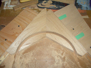
nth instance within construction, we elected to form each of these interior finishings out of two distinct pieces unified at contact by epoxy and a couple of associated tenons, acquiring the rarified perpendicular configuration of grain to stress imposition we sought to achieve. As depicted below, the resultant component entailed two constituents, exhibiting a neat acute angle between the respective pieces.  For the breasthook, an assistive jig was constructed to immobilize the unfinished piece unwaveringly, permitting impartment of the center curve via a trammel and router arrangement to attain circularity.  Although bandsaws are typically utilized to address extensively non-linear cuts, the absence of this (routinely indispensable) item within our shop catalyzed additional extemporaneous improvisation to address matters, ultimately yielding a functional alternative: enlistment of a hand held jigsaw in conjunction with a supportive apparatus to achieve commenurable outcomes.


Succeeding this, we had to deviate from familiar theoretical domains of arc-lengths, radii, and angular computations, commencing the daunting process of reconciling intangible theory with physical reality. This daunting task--entailing incremental, subjective fitting and gradual alteration--was repetitive, but yielded continual positive encouragement as the realized and intended forms progressively converged to congruity. For the breasthook, the first task entails hand cut excision of the center portion that will ultimately accommodate the stem.  We performed this by inserting the breasthook into place (coaxing it as far forward as feasible) and then scribing the position of the stem's extremities onto the breasthook using a straight rule.  Then, by transferring the depth of the stem (measured) and drawn across the two outside lines squarely, we obtained a reasonable representation of the stem's outline.  Once this excess portion was eliminated, we started the process of manually trimming the angles of the sides to match the planks, as the hull's contours produce a compound angle and minute curvature that change as a function of precise position, defying the usage of mechanized techniques.  Succeeding extensive trial and fitting, we achieved sufficient breasthook-hull congruity to placate our intrinsic propensities towards aesthetic perfection.


With this shape defined, the next step encompassed elimination of surplus material to facilitate overlap for where the gunwale would rest.  Again, this initially exhibited a deceiving simplicity that belied its true attributes.  Intrinsically, there exist two factors collectively influencing matters within this element: correspondent incision depth is salient to ensure a smooth transition as the curve progresses naturally into the gunwale component, and the perpetual, inevasible notion of angle contemplation to facilitate congruency within contact surfaces.  These aspects of function and associated implications were prognosticated upon considerably preceding the execution of irreversible cuts and angles.  Conclusively, we ascertained that the plank incantation should be maintained such that the cut ran parallel to the planking.

The knees proved to be much easier to fit as the back of the boat is mainly square and the planks are more upright than at the front.  The process was essentially comparable to that employed for the breasthook--albeit appreciably expedited!

Once the pieces were satisfactorily addressed, they were subsequently counterbored and definitively anchored with a couple of stainless steel screws on each side.  The obstruction of these persistent voids will transpire at a future juncture.

Gunwales

Superficially analyzed, fitting the gunwales seemed relatively straightforward. We took the gunwale (two pieces of oak were scarfed and glued up with epoxy to create a long board) and imposed a progressive taper (about half the thickness of the gunwale) at both extrema to alleviate the ocular abruptness of member truncation and impart aesthetic fluidity. Subsequently, we clamped one end onto the shear strake just short of the stem and transferred the angle of the stem on to the gunwale through utilization of a small piece of wood, estimating the approximate angle through the thickness of the gunwale. We then cut both angles and checked the fit of the gunwale, made slight alterations, and then proceeded to clamp the outer gunwale along the length of the boat, acknowledging that the extra length that protruded beyond the transom would be easy to cut off with a handsaw once the gunwales were all completed.

In effectual dichotomy to its exterior counterpart, inwale conception constitutes a redoubtable prospect!  Innately instransigent within linear rigidity, this structural oak component tenaciously resisted numerous valiant attempts to forcibly impose morphological congruency, generating resultant consternation. In conjunction, implications arose from origins within the inflexibility of gunwale elements, as the inherent immalleable resistivity impeded efficacious measurement and trial insertion. Emergent hesitation catalyzed by cognizance of such notions was subsequently exacerbated by a suffusive consciousness of aesthetic prominence ascribed to these boat constituents upon predication of evident visibility.

Consequently, a rational prudence and circumspection characterized our general approach to inwale confrontment, entailing a progressive truncation protocol to incrementally abbreviate an initially-excessive length to hull correspondence. Demonstrating an atypically blasé confidence attributable to rarified perceptions of process infallability, the gradualized advancement commenced: eliminate a near-indiscernible quantity of wood, analyze length comparatively with existent dimensions, repeat tautologically. Inauspiciously, however, a minute threshold appears to differentiate between length acuity (permitting successful insertion) and excessive shortness (a concept manifest within our initial attempt, wherein we were about a 1/4" short and experienced the elicitment of unbridled, indignant expressions!!!!)  Fortuitiously, marginal craft asymmetry generated sufficient differentiation between the proportionality of repective lateral polarities, permitting utilization of the initial member within the alternative location.  Evidently, the didactic lesson portrayed within this salvaged debacle indicates the salience of executing construction within a descending magnitude fashion to facilitate employment of erred stock within functional surrogate capacities. However, retrospective analysis affirms the ideality of a tertiary approach: composing an emulative gunwale from inexpensive stock  to obtain optimal dimensions preceding transferrence to consequential material, as this proposition minimizes inherent risk and yields incomparable expediency. Indisputably, the first-time nature of this construction attempt invokes affliction with tribulations evaded by inveterate participants, but our intrinsic ebullience persists undaunted.


Once the two gunwales fabricated and conducively situated, the subsequent component necessitated within progressive advencement comprised integration of the structurally-supportive blocking elements that reinforce the internal gunwale. Despite our prevailing orientation towards retention of accordance with specified dimensional and design aspects adumbrated within Atkin's templates, subjective aversion to the visual appearance of prescribed blocking configurations stimulated an election to deviate from the intended arrangement. The books on many matters concerning boat building are missing the many details that the amateur builder invariably deliberates extensively upon: "Should the blocks retain invariant magnitude while interim voids differ in proportions, or vice-versa?" , and "What effective approach to distinct inter-frame spacing should be utilized to maintain visual appeal?".  Succeeding appreciable analysis, tentative positioning, and conceptual visualization, a viable permutation of blocking attributes surfaced, encompassing a constant quantity of blocks within respective positions intervening between structural knees and marginal isolation magnitude alteration in compensatory accommodation for differing inter-frame dimensions.  In conjunction, conclusive decisive dictation entailed employment of square entities in contrast to archetypal canoe-indicative cambered blocks upon predication of traditionalism and subjective perceptions of pulchritude.


Once everything was decided upon it was a relatively straightforward task to counterbore and screw the inner and outer gunwales together and to screw the frames to the gunwales.

Still more adjustments

After getting everything into place we started looking at the gunwales and decided that the placement of the quarter knees and breast hook was slightly too low. So we elected to remove them and shift them up so that they are about a ¼” proud of the side planks and transom. This way we can plane/sand them down to create a nice rounded appearance. This work was straightforward and the extra holes we drilled to reposition them will be covered by the gunwales.

Although the advent of cold weather has compelled temporal aberration within construction, we intend to conclude interior components and execute finish application succeeding the emergence of springtime. Presuming the obligations associated with education/occupation are conducive to boat labor, the intentioned launch timeframe of May appears persistently feasible, generating substantial anticipation! 

Joe Lapstrake

Sunday, October 30, 2011

The knees AKA the Frames

Okay, its been way too long since the last post--too much living not enough blogging!

The boat has really been moving along since last winter and there is much to report here--I will try to get a bunch of posts together here quickly, so those of you who have been following along will have much to read and see....

I started out calling these side knees as defined on the plans and was subsequently informed that they are often referred to as the frames. But regardless of what you want to call them, they were really difficult to make and to install.


Our plans called for all of the frames with the exception of the two at the front of the boat to be parallel with the bottom planking and the transom. To do this each of the frames must be canted such that it is not perpendicular to the side planking. As a result there are lots of bevels to plane and cut.


Trial and error fitting

I started by making rough models of each frame prior to committing the angles to oak. But even so each frame went back and forth, back and forth, and back and forth many more times between the bench vise and the boat for custom fitting—hand planning the angle on the plank side, hand cutting out the notch for the chine, and chiseling out the curve for the quarter round. After much work and when I thought that I finally had each frame looking good I cut the final bottom angle on each frame in two directions, across the boat and front to back (a compound cut).


Marking Gunwale position
 Installation would have happened much sooner than it did but, it was a two person job, one to hold the frame in place and the other to drill the pilot holes for the screws. In fact the whole installation of the frames was the subject of much debate on the Wooden Boat Forum when I posted about attaching the planks to the frames. It seems that Atkins has drawn the frames in this boat somewhat uniquely in comparison to what other designer do. Atkins’ frame is narrow at the top and quite wide at the bottom, whereas most frames tend to be more or less the same width throughout their entire length. Consequently the traditional method of securing the planks to the frames is to use copper rivets. But in my case that would necessitate having a 6-7” rivet for the bottom plank. Since I didn’t have rivets that long nor a small diameter drill bit that long this was not an option for me. Instead, I choose to run a couple of 3” screws up through the planking into the bottom of each frame. The concern here of course is that the end grain of the frames is not very strong and will fail over time. I had speculated that Atkins must have drawn the frames the way he did (wide at the bottom and touching the bottom planks) to add additional strength to the craft. This belief was confirmed by another member of the Wooden Boat Forum who noted that the plans he had to another Atkin’s design had a note that indicated the frames were to be attached to the bottom planking. Regardless one of the keys to making a chined boat strong is to ensure that the chine is screwed into the frames (note all the grain is perpendicular to the screws and that is very strong).


I did not however want to screw every plank to the each frame as this would mean that I would have to fill each of these holes and I was concerned about the holding strength of our thin planks once they were counterbored to hold a screw. So I settled on a plan to use ringed copper nails to attach the planks and made the arrangements to procure enough to secure each plank to each of the frames. However, I experienced nothing but grief with the installation of the first nail.  I must not have drilled the hole deep enough (although I was at the extent of my drill bit) and as soon as the copper nail struck the oak without a pilot hole it promptly bent over.  Extraction of a ringed nail is virtually impossible, so I cut it off close to the surface and went away wondering what to do now.

Plugs already in place
Eventually, a light blub went off and made me wonder what I was thinking all along.  What I realized was that because I would be putting the screw through a strake lap my wood thickness was actually doubled.  I would have lots of wood to countersink the screws and plug them.  So I merrily proceeded to drill and fasten each plank to the frames. 

Tuesday, December 21, 2010

Centerboard

The centerboard was probably one of the more interesting challenges in building the boat so far. Getting the basic shape was just a matter of taking the measurements off the plans and marking it out on a piece of plywood. Again, I used my router trammel setup to cut the big curve at the one end and the jigsaw for the smaller curves. 

The plans did not have any information on how to shape the centerboard though so it was off to the Internet for another lesson and to solicit advice. A big thanks to everyone who is willing to share and help, it is invaluable to first timers like us. We learned that a good rule of thumb is to shape the centerboard with the trailing edge being half the width of the leading edge. And that the bottom 6-8” of the centerboard should be shaped to a thin edge (we went with ~1/4”). Shaping was done by hand with a plane and basically the shape was determined by “eye balling” it. Plywood really is easy to work with in this way as you can see exactly how many “plys” you have cut through all the way along. The leading edge was rounded over using a router and lightly sanded smooth.


Roughed out centerboard

Taper on bottom edge


With the final shape determined it was on to addressing the two lead weights that keep the centerboard in the water during sailing. We made the holes with a small trammel jig that I have for my router—a vintage original Black & Decker jig from the 60’s? that has only seen service a handful of times. Screws were then drilled on the inside of the holes and the heads left protruding by approximately 5/8”. The molten lead will form around these and keep the lead from falling out as it cools and contracts.

All set to pour the molten lead

A view of the whole centerboard

We had read on the Internet that some people have used old tire weights as a source of free lead. Being frugally minded this seemed like the best way to go, so off to my local Costco to ask them if they would help me out. The guy I spoke with was more than eager to help but a little apologetic that they didn’t have much old lead around that day. Still he filled a little bag for me and off I went as happy as can be. Once home we ran a few calculations to determine exactly how much lead we really needed. It was just a matter of a little geometry and specific weight calculations to determine that we needed almost twice as much as my little bag contained. No troubles though, I just stopped by Costco again the following week and got a little larger bag this time.


Now on to the fun stuff, melting and pouring the lead. Everyone knows that lead isn’t good for you so some precautions are necessary to minimize your exposure to harmful lead fumes. Even though I did grow up in the era of leaded gasoline and the fact that this would be a one time job I decided to take no chances. The lead would be melted outside in a can on a propane burner and a large fan was positioned to blow the fumes downwind and away from me.


Fan and melting pot setup


With everything set up properly I lit the burner and started the melting process. Not much happened at first but then some of the lead started to melt so I added more. Still some of the lead was clearly not melting. A little probing and I realized that some of the non-melted material was the steel section of the lead weights that is used to attach the weights to the tire rim. I started carefully removing these with a pair of pliers. Looking at the rest of the lead mass, some molten and some still in its original state I realized that there are two distinct types of lead weights, ones that are obviously lead and others that seem to be made of another type of material that will not easily melt (these weights are much harder and do not bend easily).


Cauldron of melting lead


This revelation meant that I would not have enough molten lead to pour the two weights in one pour…..so I decided to pack the holes with larger pieces of the non-lead weights and then pour my molten lead around these rather than going through the whole process of securing more lead weights and another pour. Thankfully it worked out perfectly, I used all of the molten lead and both of the holes were full. The actual pour was both rush and terrifying at the same time…I would do it again in a heart beat.

The pour


The finished result

Once the lead was cold I filed the tops until they were smooth to the surface of the centerboard and then used a little bondo to fill in any imperfections on the whole centerboard. To add strength to the centerboard we decided to cover it with 4 oz fiberglass. However, before we could start the fiberglassing I drilled a hole for the centerboard pin and inserted a short section of ½” copper pipe and epoxied it in place. The pipe will serve as a sleeve for the pin and allow the centerboard to rotate freely if we can find the correct sized rod for the pin (I understand that a 9/16” bolt is a perfect match). But, that is a problem for later.


Centerboard with copper pipe epoxied in place

First, we cut the fiberglass cloth to size by wrapping it around the centerboard and marking directly on cloth where to cut. With the cloth cut, we now had to decide how to proceed. Do we try to apply the fiberglass cloth to the entire centerboard in a single application, or do we tackle one side at a time? I could not see how it would be possible support the wet board to do the whole job in a single application so I decided to do one side at a time. With the glass in place, I wet out one side of the glass completely working from the middle to the edges. At the edges I just left them floating beyond the edge of the plywood. When the epoxy dried, I just trimmed off the overhanging hardened cloth with a sharp knife—very slick. The only difficulty I encountered glassing the second side was dealing with the leading edge. What I discovered was that you have to be really careful to keep the glass tight and not to apply too much epoxy or it will run onto the already hardened side. The final step will be to apply another one or two plies of glass cloth to the bottom edge (and maybe the leading edge too) to reinforce this area (note: after the initial glassing there is no fiberglass on the bottom edge). I haven’t finished this step yet but will get around to it in the near future. We also plan to paint the centerboard.

First side glassed

Second side glassed


Friday, November 19, 2010

Centerboard Case

No doubt you have noticed that during the finishing process time was flying by and little was getting done on the boat, to combat that I started work concurrently on the centerboard and the case. The plans called for a solid mahogany case and centerboard but, I didn’t have that much mahogany kicking around and I didn’t feel like buying another mahogany plank—too cheap I guess. So we elected to build everything out of plywood, cheap exterior grade plywood.


Stern spacer and the two sides of the case
For the case I glued a sheet of 1/8” mahogany plywood to the 5/8” ply so that the exterior of the case will match the mahogany on the inside of the boat. Cutting out the case was just a matter of following the plans.  The stern end of our case is curved (following the shape of the centerboard) and was built up from two pieces of 5/8" ply epoxied together and cut using a router on a trammel.  It was a little tricky to match the bottom curvature of the boat but with a trial and error approach the shape came together.

Trial fitting the two sides
Atkins has an interesting way of dealing with the centerboard pin though. In most boats that I have seen a hole is drilled through the centerboard case and then that hole is sealed off on each side of the case by some elaborate means. Atkins instead has you cut a channel in each side of the case that secures the centerboard pin on each side. The centerboard can move up and down vertically along this channel but is constrained from moving the other two dimensions; fore and aft and starboard and port (seemed like a good time to start using some nautical terms). I have elected to run a piece of UHMW (ultra-high molecular weight) plastic that I purchased from Lee Valley Tools in the channel and to drill a hole in that to position the centerboard pin. I believe that if I run a piece of UHMW the full length of the channel then the vertical movement will also to stopped. We plan to find a way to make the top of the centerboard case removable so that we can access the centerboard easily if needed.

To make the case watertight we applied a few coats of epoxy to the interior surfaces prior to screwing the two halves together. A thin coat of Sika was applied to the joints and the whole case was screwed together with 2 ½ stainless steel screws.
Assembling the case note the Sika and the channel

The scary bit: cutting the slot in the bottom planking for the centerboard to pass through.  I must admit that this was a little intimidating.  A lot of hard work had gone into installing the bottom planking and some how it just didn’t seem right to start cutting a huge hole right down the middle of it.  I also have to admit that it still doesn’t make sense to me that you can cut a board in half that is only supported on each end and not have it sag significantly in the middle—but it didn’t.  So after carefully measuring (twice at least) and marking its position it was time to take the plunge.  First I drilled a hole at each end and then marked a line to each side of the hole.  Then with jigsaw in hand I carefully cut at least a 1/8” to the inside of the marked line (what a chicken I am) all along thinking that I will finish cut it from the bottom with a router using a pilot bearing bit.  Like most of our fears they are all between our ears and are never realized—everything went really smoothly.


All marked and in the midst of cutting

There's a hole in my boat
 Prior to installing the centerboard case we laid down a generous bead of Sikaflex and then carefully lowered the case into position (we pre-marked its location to facilitate this process). With the case in position a long clamp was dropped down through the case so that it made contact on both the exterior of the bottom planking and the top of the case. It was then lightly tightened before a second clamp was positioned at the opposite end and tightened. At this point we double checked to ensure that the case was square and then proceeded to apply a little more pressure to each of the clamps—not too much though as we did not want to squeeze out all of the Sika. We left the Sika to cure for a couple of days before screwing the case in from the bottom side through the planking. The case is approximately 48” long and on average our planks are 3”, so I expect that we will put over 32, 3” stainless steel screws into the case from the bottom—that ought to hold it!

All done
A picture that shows the centerpin channel from the top

Tuesday, November 2, 2010

Interior Finish

Flipping the boat over resulted in several revelations. The first was that all of a sudden the boat seems really big, surprisingly big, much bigger than we had imagined it when it was upside down. The second was that our planking looked pretty good, both the bottom and side planking had turned up well. The third was that we had been quite generous with our use of Sika to seal the planks. While it is tremendous to know that the boat is well-sealed and shouldn’t leak we didn’t quite know what to expect the interior would look like once we cleaned up the excess Sika. If you decide to follow our approach be forewarned that cleaning up the squeeze-out can be quite time consuming. We went at it with a variety of tools, chisels, cabinet scraper, exacto knife, and paint scraper. Each has its application and we found that no one tool was successful in all situations. But slowly but surely we eventually removed the entire squeeze-out. Whoo-hoo!


Transom prepped for staining
 And finally the fourth revelation was that we had over cut the width of the gains in some instances and while on the outside of the boat the planks were flush there was a small gap on the inside. To tidy this up we carefully selected gain and color matched mahogany planking cut-offs and cut and glued slivers of matching wood into the over cut gains. Another pain staking process that you just want to get over so that you can get on with the real work.
Bow prepped for staining

The real work was to set our hands to the construction of the centerboard and its case. But the more we thought about it the more set we became in our belief that now was also the time to finish the interior planking of the boat before it became cluttered up with side knees, and bench supports, and benches. Now was the last opportunity we would have to have complete and easy access to the side planks.

Of course the question was how to finish the interior? From our investigations there are as many ways to finish a boat as there are ships in the water it seemed. At first we had decided to go with an oil based solution. Lee Valley Tools sells a couple of products that seemed like good candidates, Deftoil (Marine or Exterior Finish) or Tung oil. A couple of years ago we had used Tung oil on our outdoor cedar planters and had been reasonably happy with the results. The nice thing about this product is that it has a smooth finish and you can really still feel the wood. We also liked the Deftoil because it has some dye in it that we thought would be good for evening out the differences in the natural coloring (some light and some dark) of our mahogany planking. But further reading about oil type finishes revealed that they have a tendency to turn black over time. And I can see this taking place on the planters now that they are two years old. I just couldn’t imagine sanding down the whole interior every 2 years and refinishing!

After considerable time spent investigating our other options we decided that we would first stain and then varnish the interior. Choosing the stain was pretty straightforward, a trip to the local big box lumber store provided us with all the ammo we needed to narrow the choice to a couple of stain colors. We bought both of them and stained both a light and dark plank to see how they would look. In the end we choose Minwax “Red Chestnut” for the stain. The process of staining the wood was really simple and quick—a quick application with a rag, wait, and then a light buff to pick any excess.

The choice of varnish was another long drawn out process as we had read a lot about Behr Spar Varnish and how wonderful it is—apparently an original formulation that has been made for years and years, inexpensive, and easy to apply. It is available at Home Depot in Canada but no longer available in the US, I do not know why. Our local store had 1 litre cans of gloss (we wanted to use gloss vs. satin because it has more UV protection and had decided to follow that with satin if we found the gloss too reflective) but no 4 litre cans, the pricing was $15/ 1 litre can and $35/ 4 litre can so naturally I wanted to get my hands on the 4 litre can. So I had them do an inventory check of all the surrounding stores. What followed was totally comical, the sales clerk would first check availability on the in-store computer and then phone a store that according to the computer had inventory only to discover that the product wasn’t actually in the store. He repeated this process for at least three of their stores until eventually he came back and basically said that it wasn’t available. On a whim a couple of days later I decided to hit a couple of the stores that the sales clerk couldn’t get a phone verification from because the stores were just too busy. The first store was a bust but at the next store I hit the mother load, they had 10 cans of the stuff—hoarding it no doubt!

By now I was all pumped up to start varnishing but needed to wait for the right weather, humidity below 60% and temperature above 60F as varnish can blush if the humidity is too high. And I needed a few consecutive days as the plan was to apply 8 coats and I needed at least 12 hours between coats but no more than 24 hours. In a perfect world 4 days would be sufficient. What followed was the coldest and wettest fall in ages. Every time it looked promising the forecast would change and the rain would come again—this went on for weeks. As it turned out I applied a couple of coats using a foam brush and then it rained. So I waited, then sanded. Sanding turned out to be a really time consuming process, each re-sand would take ~2.5 hours. All those copper roves look nice but really slow down sanding and the narrow planks make it difficult to use a powered sander so most of the work was done by hand. Here is how the work progressed, first I applied 2 coats then sanded, then another 2 coats and sanded, then another 2 coats and sanded, then I applied coat 7 and sanded and then finally coat 8. In the end I was happy with the way the finish looked and evened out the color differences in our boards—the scarf joints have all but disappeared. But in all honesty I can tell you the finish is not furniture smooth and silky but it should be functional—it is a boat after all! We still have bluff the transom with some really fine grit to smooth it out further but, that will have to wait for another day.

Finishing done, starting work on side knees

Note marks for location of molds and centerboard on green tape

Lessons learned:

1. Finish sand your planks before installing them as sanding around the roves is slow and painstaking work.

2. Mark location of molds on floor, chine, and top of planks (both sides or you will be wondering which is which).

3. If you have access to a sprayer, use it, the varnish will go on smoother—although for the cost the foam brush did a great job.

4. Get sand paper that will not load up quickly—I used 220 grit especially designed for sanding varnish.

5. The roves like to hold vanish and will eventually start a small run—I wish I had some sage advise on how to address this problem but, I do not, good luck!


The next post will cover the centerboard and its case, this work proceeded in conjunction with the finishing work.

Tuesday, September 21, 2010

Bottoms Up!

It was with some anticipation that we launched into planking the bottom as we would now be able to use those amazing clear fir boards that we had bought on Kijiji back in April. This was quite possibly the buy of the century. The ad read, “Clear Douglas Fir 3/4"x3'"x5' 0.10/linear foot Lumber” (~$0.50 per board foot). The material was off-cuts from a siding job and although the actual widths of the boards varied between 2-3.5” it was absolutely clear, straight grained, old growth fir. What a coup!

At first the prospect of planking seemed quite straight forward, joint the two edges of each board dead flat, apply a thin bead of Sikaflex, clamp the over hanging ends of each board securely to the previous plank until the fit is tight, counter bore a screw hole through the plank and into the chine, and then drive home a 1 ¼” stainless steel screw. Repeat until you reach the front of the boat, then cut off the overhanging pieces flush to the garboard plank.

Of course we agonized over planning a slight angle on each plank so that we would get a slight “v” between each set of planks. We understand that on many traditional boats this is standard practice and that these “v” joints would subsequently be chinked with cotton. But in the end we decided that a modern sealant like Sikaflex should provide similar performance characteristics to the old world methods, plus it would be a lot easier to implement.

We started at the transom and worked our way forward. The first plank was really easy, just line it up parallel to the transom and screw it down all the way around. The work progressed quite quickly for the first couple of feet until we encountered our first challenge—clamping the boards together. As we approached the 2 foot mark we realized that our 2 foot quick grip clamps would soon on longer be long enough to clamp the board together. You are probably thinking, “just get longer clamps”, and while that would an acceptable solution for a while it would not be a fix all as our longest clamp is 6’. Instead, we started to stagger the amount of overlap from side to side so that we would always have a point of purchase on each side. Although there were a few occasions where we ended up drilling a hole in the overhanging plank so we could get a clamp in place.

On the first day we decided to plank approximately 5 feet and then to put a couple of clamps on the whole set up to draw it up nice and tight as there were a few small gaps starting to form in the middle of the planks. To address any up/down crown or sagging in the planks we initially put light pressure on the clamps and then carefully knocked individual planks up/down until the whole area was generally quite flat. We left the clamps in place for several days to allow the Sika to set before proceeding with any further.

The next 5 feet were straight forward as we had established a good routine that quickly allowed us to put the bottom planks on. In fact we spent more time prepping the boards and selecting which boards would go where than actually installing them. We did come up with a good trick for clamping the next 5 feet set up together to close any small gaps that may have formed. We clamped a couple of 2x4’s to our molds that had a groove cut in it the exact size of the end of our quick clamps. Then by reversing our clamps to make them into spreaders we fit the other end into another small groove that we cut into our caul. The picture is worth a thousand words….


As you can see from the photos we trimmed the overlap excess in between the 2nd and 3rd sections of planking and started the process of hand planning the bottom to a smooth finish while the Sika set. The sides were first roughly cut off with a circular saw (being very careful!) and then fine tuned with a block plane. This was slow and arduous work slicing through end grain—again a sharp plane is invaluable for this type of work. The last plank was interesting, it was cut to fit snuggly against the stem and was generously slathered with Sika to prevent water penetration before it was forced in with a mallet. This effectively closed up any possible gaps that may have existed between the middles of the last section of planking.


We were extremely pleased with the final appearance of the bottom and were paid the highest of compliments when someone asked if the bottom was a single piece of wood.


With the bottom all done it was time to build the skeg—the sternward extension of the keel. The plans called for a piece of 7/8” softwood but now that we have it made I am considering building another out of hardwood as I am concerned about the durability of the softwood version. It was a little tricky to get the same curve on the bottom of the skeg as the bottom of the boat but after a little trial and error we managed a good fit. We elected to wait to install the skeg and the two bottom rub rails until after the bottom is painted. Hopefully, this will result a better layer of water protection than a bare wood to wood joint.


You can really see the curve in the bottom of the boat
After a couple of days of letting the Sika dry on the last set of planks we were eager to turn the boat over so one night just after we returned from being out we gathered the family together—the four of us. The two boys took the stem and I lifted the stern. Straight up at first to clear the molds and then we slowly started to rotate the boat until it was right side up. About half way through my bad shoulder went crazy and it felt like I had dislocated it. As it turned out I was okay after about half an hour but, did it ever hurt at the time! Now we really had a sense that we are building a boat. We also incredibly taken by how big the boat seemed.


Joe Lapstrake

Sunday, September 12, 2010

The Procession of The Strakes


After completing all of the preparatory work, we finally had the opportunity to begin the process of planking the craft. Although, on most craft, the garboard is inherently difficult to shape and attach because of the tight curves that it must accept, Willy’s first planks were a simple matter. This can be largely attributed to the flat-bottomed construction of the hull, not our boatbuilding prowess. However, after completing these strakes, we were faced with a new challenge. Unlike the bottom boards, which are affixed to the chine using screws, the remainder of the planks (8 in total) are fastened to the previous strake with copper rivets. Being a non-ferrous metal, copper is fairly inert in moist environments, which makes it an ideal candidate for this application. Spaced at 3½-inch intervals along each lap, we had a total of almost 400 rivets to install over the entire craft. Needless to say, we were somewhat daunted by this prospect. Fortunately, although this process does require the builder to develop a certain rhythm, it is, in reality, quite simple. The most important resources in this procedure are a willing assistant and a surplus of time, as it can be rather lengthy. Below, the system is condensed into five steps. Please recognize that, while this is a brief overview of the process, more detailed information concerning this method is outlined in many boatbuilding books.


1. Bore a slightly undersized hole in the hull at the intended location of the rivet. After the nail is inserted, this will create compressive forces on the wood that effectively seal the joint from water penetration.

2. Counterbore the hole on the outer face of the board to the dimensions of the nail head. Although this step is not necessary, it helps to seat the nails flush to the hull without scarring nearby wood through overzealous use of the hammer. In addition, we also found that some of our mahogany planks so hard that it would have been very difficult to sink the nail heads without counterboring them. If you are have softwood planking this step may not be necessary.

3. Drive the nail ¾ of its length into the pre-drilled hole. At this point, the assistant places the rove (in the rivet punch) on the opposite side of the plank. Proceed to drive the nail until level with the exterior surface of the hull. By this point, the rove should be snug to the plank’s interior. However, if this is not the case, a few taps on the punch with a hammer will remedy the situation.

4. Cut the protruding nail off, leaving it about 1/8” proud of the apex of the conical rove. While the exterior individual braces the nail head, peen the excess metal into an even, symmetrical dome, preventing the nail from retracting the future.

5. Repeat 399 times.


Although riveting is somewhat time-consuming, mundane work, if both workers are able to develop a sense of cadence, it is possible to affix a strake in little over an hour.


Close up of exterior hull rivets


Seeing as the process used for each subsequent plank is identical to the system outlined above, it would seem overly repetitive to give a detailed account of each strake. Instead, we have consolidated this task into a series of photographs, allowing the reader to witness the accomplishment of hours of our labour in a convenient photographic form.


One strake per side


Two strakes per side
Three strakes per side

Three pictures of four strakes


Done - Five strakes


Now that all of the constituent elements of the hull sides are completed, the next item on our agenda is that of bottom planking. Seeing that Willy is of flat-bottomed, cross-planked construction, we anticipate that this will be a fairly straightforward task. Tune in for the next installment soon!

Joe Lap